Sunday, February 3, 2013

It Starts! And it's loud....

I've been really busy trying to get the car done, so I haven't had time to make new posts in a while.  Anyway, since my last post I've done a lot!  I finished installing the Steeroids, Hydroboost, and power steering system.  I got the exhaust installed which was a real treat because of the Steeroids system and other clearance issues.  The one of the header tubes had to be dented...   A LOT!  I also even started installing the suspension.  I've got the new aluminum upper control arms in, as well as the spreader bar.  I've got the lower control arm, shock, and spring off the passenger side.  Was waiting to see if I had a fuel pump leak before installing the new pieces.


Anyway, last weekend we tried starting the engine.  Which we successfully did.  Unfortunately, when the engine was dyno'd they used the oil pressure oil on the top corner of the block and didn't plug it when they were done.  So we ended up spewing oil all over the firewall and floor.  However, getting all the fluids in showed me where I hadn't done the fittings good enough.  The heater core fitting on the water pump had to be redone, the check value on the carb fuel line feed needing sealing, and the connections to the fuel pump were leaking.

Fixing the fuel pump fittings was a pain.  To get to them I had to take the lower control arm off.  Even then it was difficult.  I ended up chewing up the threads on the fittings trying to get it back together that I ended up having to replace the whole thing.  This time I made the hose portion longer so it was MUCH easier to install.  Not sure why I didn't do that in the first place.  Another fun thing was the temperature sensor.  Apparently aftermarket heads all have 3/8" NPT fittings, but all GM heads before'79 use 1/2" NPT fittings and there are no 3/8" NPT temperature sensors that work accurately with the stock gauge.  There's one that's close (WTB-510 for like a Volvo), but I already bought new sensor and couldn't take it back.  I had the thing milled down to a 3/8" NPT.  Fits perfectly now, but it definitely would have been cheaper to get the sensor that was "close".  Oh well, it'll be accurate now.

And now for the videos...

This video is right as I successfully get the engine started without having to immediately turn it off because oil is shooting out.


This next video is right after the previous one.  Don't worry about the smoke...  The new exhaust wraps are getting broken/burned in (the instructions said that's normal).  There is a considerable amount of smoke coming from the exhaust though.  At the end of the video you'll hear a really high pitched noise coming from the power steering.  I contacted the companies to find out what could have gone wrong, but the fluid is now a green/brown color and is milky instead of clear.


Friday, January 4, 2013

Rack and Pinion System & Brake Booster in the Car

Quick note...  I fixed up the post from 11/24 with better organization and pictures.  I did that post from my tablet and the interface to Blogger isn't very good.

As I mentioned in my previous post, I've had about a week and a half to work on the car without work and school interfering (just had to do family holiday things).  And now with a baby on the way, pressure is on to get this project done!  (due July 9th)

First thing I did was get the wiring done, and it looks pretty good if I don't say so myself!  I replaced a fuse box I had gotten with terminal panel because I needed just terminals to hook up to power on ignition, and the connectors for the box allowed it to touch the insulation which I didn't like.  I coated the terminal panel with liquid electrical tape (did that to the stud in the engine compartment next to the upper relay as well) just to make sure a positive terminal wasn't exposed.  The breaker on the right in the first picture is for the Vintage Air system, the two larger relays are for the electric fans, the smallest relay and the breaker on the left is for the water pump.  The upper relay is for power on ignition.  Rather than run directly off the ignition circuit, I put a relay in that's triggered by the ignition circuit.


With the wiring complete, I went on to more ambitious tasks...  The Steeroids rack-and-pinion and the Hydroboost brake booster.  I attempted to get the brake booster a few month ago and install it over a 4 day weekend, but they ended up not being able to ship it out fast enough.  For those not familiar with it, the purpose of the hydroboost system is to replace a standard vacuum brake booster with one that runs off the power steering pump.  There are several benefits to running such a system, but the main one for me is that I do not have to use the vacuum port on the intake manifold.  If you're familiar with some of my previous issues, you know that my new air gap intake, Holley style carb, and stock hood make it impossible for me to use the port without using an absolutely tiny air filter (not what I want to do...).

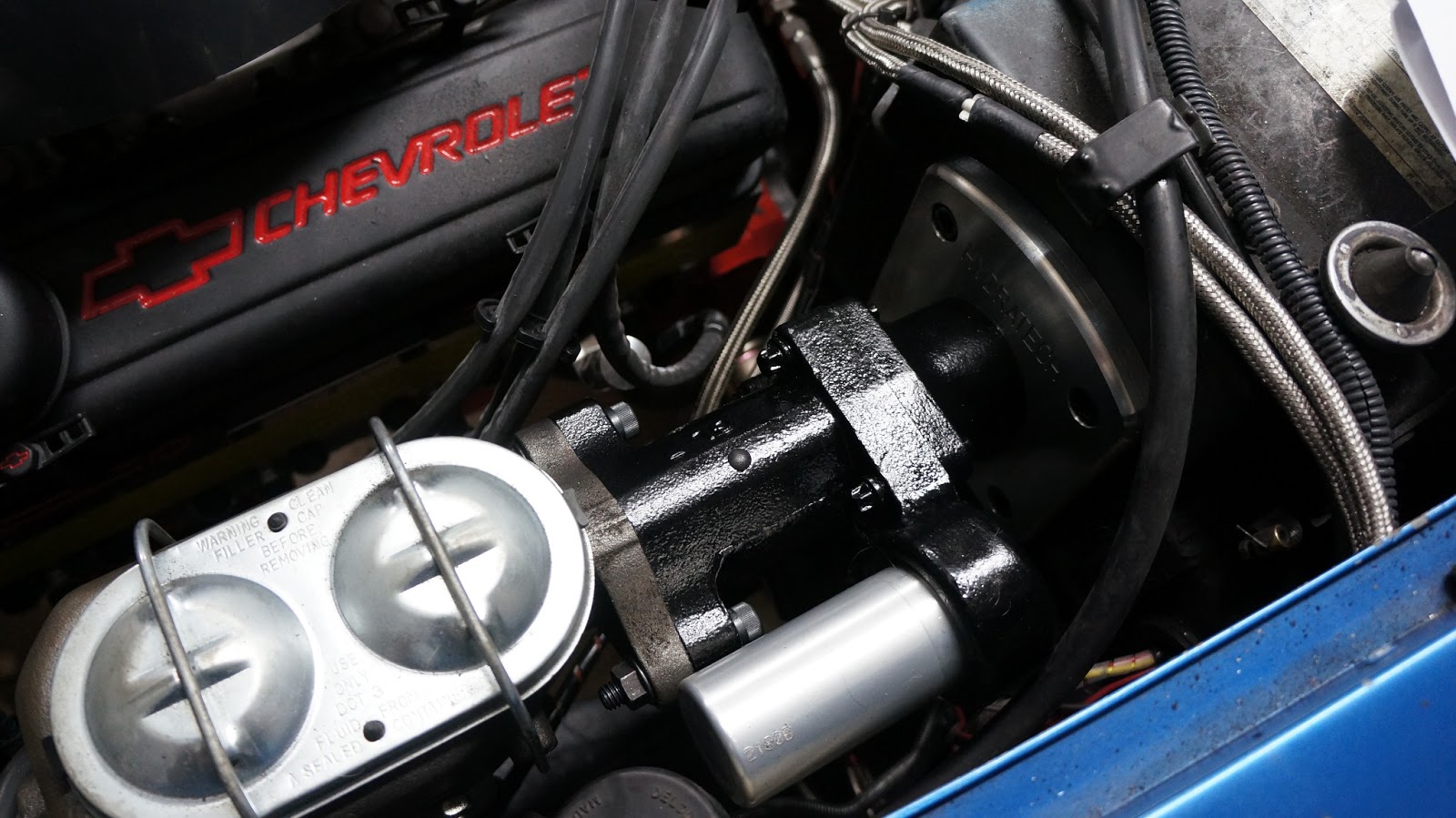
To be honest the hydroboost went on really smooth.  I had a slight issue that I had to drill out two of the mounting holes a little, but other than that, it was pretty easy.  The booster has 4 bolts that are horrible to get to with all the wiring in place that I had just done, but with a really long ratchet extension and a swivel I was able to them off and back on with minimal swearing.  I haven't hooked up the hoses yet because the Steeroids system will be hooked up as well.  Oh, and check it out...  I can actually get to the oil dipstick now!!


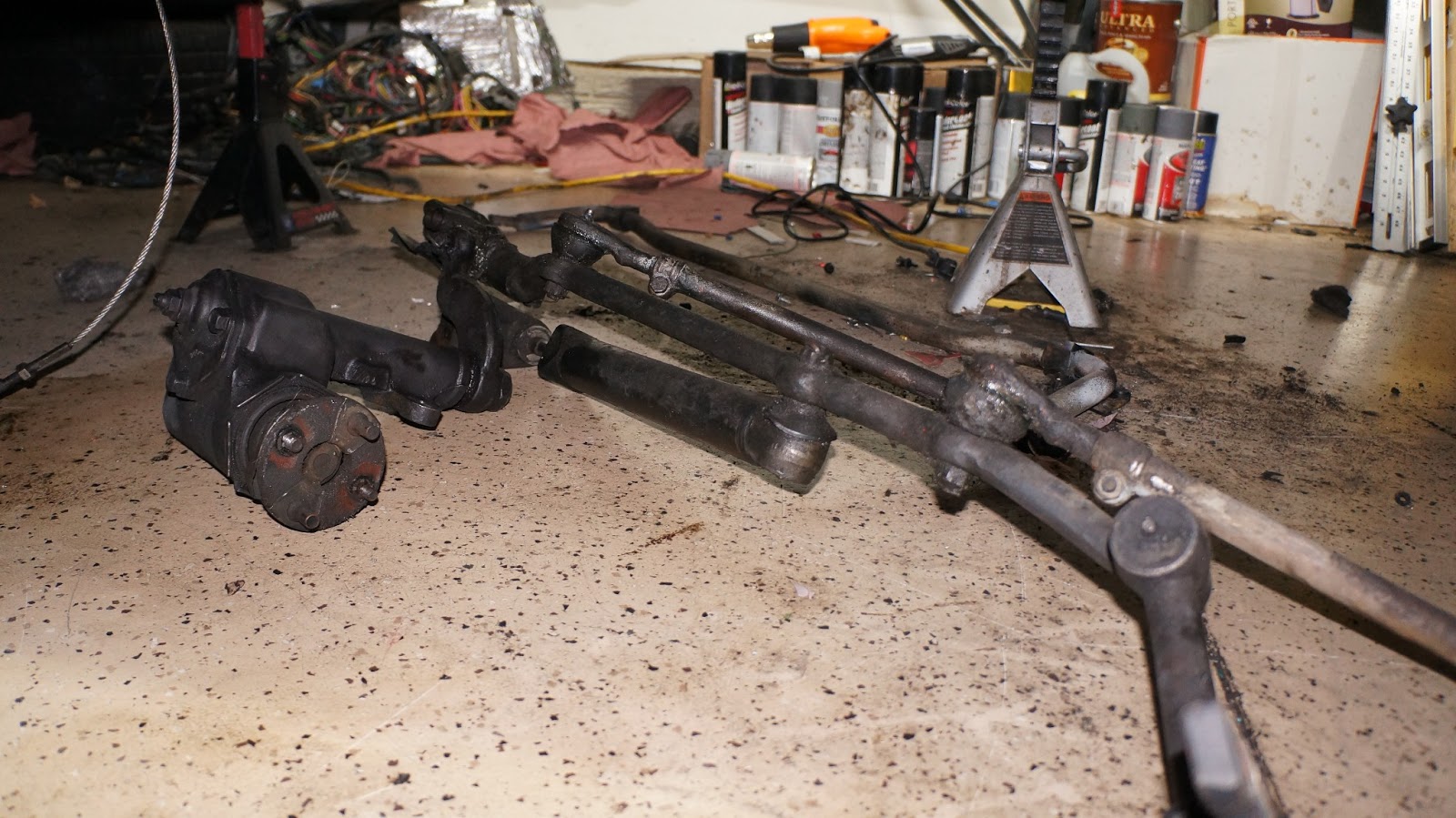
While I was installing the hydroboost, I was installing Steeroids in parallel.  A quick overview of what that is...  Essentially it's a system that replaces the entering steering system with a power rack-and-pinion system to provide much better handling.  If you've ever driven one of these old Corvettes, you know they handle like a freaking pig!  Anyway, step one was to remove the entire old system in one shot (had to got buy a pickle fork to release the tie ends).  Then you install some custom made brackets into existing holes in the chassis.  After those are installed, it's just a matter of bolting the rack-and-pinion system up to the new brackets.  All pretty simple and straight forward at this point.

Next, you have to install this custom u-joint system that connects the steering column up to the rack-and-pinion.  And now for trouble.  I couldn't get the steering column spline into the joint.  It was just a hair too large.  I contacted the manufacturer (Speed Direct) and they said to take a file to each one of the grooves on the column and the joint until I can get it on.  After 3.5 hours of filing and sanding, I was finally able to get the joint onto the steering column far enough.  That was a huge pain, but tech department said I needed to get it all the way so the joints wouldn't bind up and length was right.  I was so excited when I finally get it on and working that I had to take a video.


With the work that I'm doing on the steering and brake booster, I'm currently not able to put the exhaust manifolds back on yet.  If those were in, this would take much longer or even be impossible to do.  That hasn't stopped me from getting them ready to be put in.  I now have my Thermo-Tec exhaust wrap on the headers and it had been sprayed with their high heat coating for protection and additional insulation.  Once I done putting the hoses on these new systems, the exhaust is ready to go.


I have done a few other things...  I've sized the Lokar transmission cooler dipstick to the correct length to indicate full and I've also started configuring the shifter (that one's kinda tricky).  I also started connecting up the transmission cooler lines to the radiator.  Fortunately, the connections were really easy (contrary to what I originally though).  Now it's just a matter of connecting up the hard line to the flex lines and filling the transmission with fluid.  BTO makes you do some pressure and temperature tests on the transmission once it's installed to ensure it was done correctly.  Both the sensors are now installed, but I have no idea how I'm going to get them into the cabin with the side pipes...


Oh and here's a couple pictures from a few weeks ago.  This is the fuel line hooked up...


Thursday, December 27, 2012

Quick update after doing some work

Alright I know it's been months since I made a post but I'm finally working on the car again!  Honestly it feels great to be able to do this again after busting my ass for work for months and then having school on top of that.  My goal is to start the car before the end of the year.  As of right now, it's looking like that's a realistic goal to meet.

The shark bite suspension and steeroids have been showing up for the past couple weeks.  The only part that hasn't shown up is both the upper and lower control arms but the company said they were supposed to ship last Friday.  I expect to see them soon.  Also, Ecklers started carrying the retrosound sums radio and had a sale last week.  So I now have the last piece of the stereo coming to get it fully functional.  Good thing too because I sold the original radio to a guy in Missouri that's restoring a t-top.

Some things I've been working on...
Got the fuel line completely hooked up to the engine.
Rebuilt the crankcase ventilation and evap canister setup with braided stainless steel AN hoses and fittings.
Finished wiring the water pump, fans, electric choke, and AC system in the engine compartment.
Reconditioned the gas peddle and finished hooking up the throttle cables.
Pulled the speaker wire I had ran to the back and reran just the RCA cable and remote wire.
Nearly finished wiring up the interior (including the transmission TCC circuit).
Tried to follow the BTO instructions for the TV Made Easy system by changing the spring for the TV cable only to figure out that I couldn't which made a big mess...  need to contact them about that...
Started putting the exhaust wrap on the headers.  One is done but didn't have enough for the other.

That's it for now!  Pictures will be posted later with more updates as I continue working.

Saturday, November 24, 2012

Wish i had more time to work... maybe soon (old unpublished post)

About 2 months ago I started working heavy overtime at work.  Five weeks ago it was made mandatory to work at least 50 hours per week for my entire department.  Given that I've had to neglect school for work, I've had very little time to work on the Corvette at all.  On top of all that, I started having big problems with my WRX again and I was out a car for whole days at a time.  Finally got fed up with dealing with the car so I decided to trade it in.  After lots of test driving and research I ended up getting a 2013 Dodge Charger R/T Road & Track with the Super Track Pak.  It's a lot of fun with it's 370 hp, 395 ft-lbs torque, performance steering and suspension, and 3.07 performance differential.  I only wish it came with a manual transmission...  Enough with my issues on to what's new with the C3.

I haven't been able to concentrate on one piece of the other, so multiple things are half done.  First, I started connecting up the throttle cables (main and cruise).  This required that I patch the hole where the original throttle cable went because the Lokar one has a different shaped mount.  Took a piece of aluminum stock and bent it so that it could be secured where the old hole was.  A little black paint and it's ready for the throttle cable.  I had to let it dry, but then never came back to finish the project.


Next I started back on the wiring.  The transmission has a kickdown circuit that needs to be connected to the ignition line as does the Vintage Air system, water pump, fans, and carburetor.  I mounted the relays for the electric fans and water pump on the cover where the old A/C system used to be.  That's where I'd mounted the battery terminal I'd installed.  There's lots of room over there to work with.  There's a couple breakers installed there too.  Using a new heat gun, I was able to get most of the complicated wiring done in the engine compartment.  Now I just need to finish running the lines to the ignition power and to each of the devices.  I didn't like how I had done the fuse box previously so I ordered a different style one with a cover.  Again, this is where I stopped...


A while back I decided I didn't like how the crankcase ventilation line and the evap canister turned out, so I ordered the parts to connect them to the carb with AN hose.  I had enough left-over stainless braided hose, so it was just a matter of getting the right connectors.  It ended up being a 6AN hose finisher (worm gear clamp) on the crankcase and carb because they were barbed connections, but then standard AN hose end for the others.  There two 6AN hose ends, a 6AN T, a 6AN coupler, a 6AN to 4AN reducer, and then finally a 4AN hose end for the evap hose (it already had a hose finisher on the other end).  This was all done using nickel plated connectors.  After destroying my first 4AN hose end, I decided that I'll be doing the nylon/Kevlar braided hose from now on.  Going this route was much more expensive than using the Hose Candy (which I do not recommend unless you use their hose), but it looks WAY better and is more secure.  This I actually finished!


The last thing I started but then didn't finish was hooking up the fuel line.  I'd hooked the carb up, but then left it because it was going to take too long.  Well, I finally got back to it.  The pump to carb line Sperry Engines had put together for me had the inline fuel filter coming right off the fuel pump.  Now if you've ever looked at where the fuel pump is on a C3, there's no way in hell I was getting that on there with the A/C compressor.  What I ended up doing was clocking the fuel pump one space clockwise so that I could fit two 90 degree NPT to 6AN adapters.  From the pump I then went up in front of the serpentine brackets and behind the belt.  From the carb I came straight out to a 90 degree hose end that connected to the fuel filter.  That's where the line coming from the pump connects up.  It actually ended up looking really clean, and it makes easy access to the fuel filter.  There's only a little wiggle in the hose, but it shouldn't be enough to cause noise or problems.  As for from the line to the pump.  I ended up having to get a 120 degree hose end so that I could connect it up.  After draining the gas tank, we sawed off the barb from the fuel line so I could attach my adapter.  It was cut with a hand saw and then deburred and cleaned.  I still had to bend the gas line a bit to make the final connection, but it even went on.  It looks pretty good, and I only chewed up the connectors a little bit (good thing they're hard to see).  The gas leaked onto some of my undercoat and it came right off.  It seems dumb that the undercoat wasn't resistant to gas, but oh well...  Just got a little bit of touch-up work do now.


I've got lots of other exciting projects ready to go...  I'll be getting on those within the next week.  I'll put some posts up this weekend about what they are.

Here's some pictures of how the A/C heater hoses turned out...

Wednesday, September 12, 2012

Started Hooking up Fuel Lines

Well, I started assembling the fuel line kit tonight.  Got the lines connected to the carb and then figured out the hoses I got for the heater aren't going to work.  Basically, because of the way the Holley style carb has its fuel lines, the line goes right over the intake fitting making it impossible to put a hose on the barb.  The only way to do it would be to use expensive AN hoses and fittings with different angle adapters.  I was second guessing my choice for the hoses anyway.  After attempting to use the pseudo-braided hose on the radiator, it left me with a low opinion of these hoses and clamps.

So I ordered a lot of different angle fittings to just try different setups.  I went with black braided hose instead of stainless because it's considerably lighter and these hoses are pretty large.  The fittings will be nickel colored which will match the compressor, condenser, and evaporator A/C lines.

Also, as far as the A/C line fittings go...  Vintage Air called me this morning.  He said, "So it looks like we're going to send you the different fitting.  I think that will be the easiest route".  I wanted to say "No sh*t...", but I stayed polite and said thank you for the help instead.  He also said that I could get the fittings crimped at a Napa store and that it shouldn't be done with a hydraulic crimper because it will damage the fitting (which is actually opposite to what I'd read online, so that was good to know).

Tuesday, September 11, 2012

The Air Cleaner Post

Ok, I said I'd post about the air cleaner but then never did.  Here's what I did...

I ordered the Spectre Cowl Induction Air Box with the flow-thru top air cleaner.  I had been debating about this because it was pretty expensive and I wasn't sold on the whole cowl induction thing.  So after posting to Corvette Forums about it and seeing plenty of other people still having this problem and often custom making air boxes, I decided to do a little more research.  I could have gotten an L88 hood, but I don't like the look of those things.  Makes the car kinda ugly.

The Spectre air box has a 1.7" drop base and claims that you only need 2.5" from the carb flange to the hood.  This is 1/2" lower than the Proform with it's 1.5" drop base.  Since the 3" just touched the hood, it seemed like 2.5" should be about perfect.
 
When the cleaner came I was impressed with the quality packing and how nice it actually looked.  I always figured Spectre for kinda cheesy looking stuff.  The problem was the cleaner didn't fit.  It was hitting the distributor even though it has a special cut-out to avoid it.  This is a standard 350 block, so maybe my carb sits a little back in relation to the block?  I don't know.  So anyway, then we discover that it was actually hitting the two bolts on the ends of the carb.  Just barely, but it was making it so the cleaner wouldn't sit flat.

Disappointed that it didn't fit out of the box and I had spent so much time looking into it, I was determined to make it fit.  So, I got out some thick duct tape, a block of wood, and a ball peen hammer.  A few well placed hits and the cleaner could sit down on the carb.  A lot of hits later, it was also able to go in next to the distributor.  Next was the hood test...


My wife helped me get the hood back on the car after I removed the cowl induction flapper and its wiring.  It had been disconnected for years anyway, but it needed to be removed because the air box is nearly a sealed compartment (not sealed in the corners).  Moment of truth....

The hood closed.  And from the look of it, the new air box sealed perfectly with the hood.  I was extremely happy...


That was until I started installing the TV Made Easy system from BTO.  The system is actually pretty large, and bracket for attaching the throttle cables actually just hits the air cleaner.  I couldn't believe it.  There was a lot of extra metal on the bracket at the top, so I decided to trim it a bit with my grinder.  A trip to Menards for a new blade and a tool to remove the blade later and I had the bracket ground down.  Now it fits!  Yey!  Lets not have any more clearance issue with the air cleaner, okay?!

Of Course The A/C Couldn't Be That Easy!

Lots of fun with the Vintage Air SureFit system for 1975 Corvette with factory air conditioning...

So according to Vintage Air, the kit is supposed to go in with only minor modifications to the car for the new duct work... Riiiight!


Alright I didn't have any problems installing the duct work adapters and converting the controls.  Now on to the rest of the kit.  First let me mention one thing.  I ordered the kit directly from Vintage Air instead of buying it through Ecklers or Zip because I was getting the March Performance serpentine kit as well.  I ordered the regular kit with three changes.  First, I had them remove the mounting bracket.  Second, I had them provide a compressor with a serpentine pulley instead of a v-belt.  Finally, I had them polish the compressor so that it would match my polished alternator.  Nothing big right?  Anyway ditching the bracket pretty much paid for the polishing, so it was all good.

The compressor went on the March bracket fine.  I had to get a longer bolt for the adjustment rod, but March provided that for free.  So the next thing after the compressor was the evaporator.

Before you put the evaporator in the car, you have to put some pipes on it and do some bracket prep (including drilling some holes in the firewall using a provided template).  Got everything ready and then went to put the thing in the car.  It didn't fit!  There's a bracket for bracing behind the passenger side dash on convertibles and a couple other models that prevents the evaporator from going in.  The bracing helps reduce cowl shake.  So I gave Vintage Air an email, here's what they said...
I have talked to our R&D tech and to one of our Dealer/Installers in Houston Texas who has done several of the 68-76 Corvette installs. None of the cars we had in-house during the design had the support brackets but my installer stated some of them did and some didn’t. He did have to remove the two lower tabs with the bolts in them for the evaporator to fit. He also stated some of the cowls are formed different than others – he has had to trim insulation back on some for the servo motor to clear and slightly modify/tweak the evaporator bracket for the bolt to go in.
Seriously?  Their research is kinda piss poor then...  The other system out for C3's (which is sold by Corvette America) called Perfect Fit takes the brackets into account.  They point them out in the instructions.  Honestly, wouldn't you think they'd put a note in the instructions and even on the catalog information about the models with install issues?

Ok, so I used a new Dremel and cut off the bracket. Whatever...  The evaporator finally fit in.  Well, on to the cover that goes on the firewall.  The holes they had me drill for that were both 1/2" off (and yes I checked like four times before drilling).  It's not only that, but there's a notch in the cover for around the mounting bolt for the evaporator.  That was off a bit too, so the Dremel came to the rescue again and I made the cut-out bigger.  There was one hole that actually fit though and that was an OEM one...  Now you're probably thinking I just didn't have it line up right.  If I had lined up the cut-out with the mount bolt, it would have been even farther off.


Next was the condenser install.  I had just finished installing a brand new radiator and radiator support.  The support kind of sucked to install by the way...  It's supposed to line up with existing holes in the radiator support and you're supposed to use the OEM bolts.  Well guess what?!  Bolt holes didn't line up and in one case there wasn't even one close so I had to drill a new one.  I also had to go get a longer bolt for one.  It's in now though.


On to my latest call with Vintage Air.  The hose kit they set me is a "mod" kit.  Which means the hose didn't come put together.  Wouldn't be a big deal except that you have to have a $5k tool to crimp the fittings on and at least one of the fittings isn't the right angle!  I double checked all my documentation and it looked like the right kit according to the title and everything.  With the #10 hose fitting on, I wouldn't be able to shut the hood.


This of course prompted me to call Vintage Air and see what was up.  They initially told me that I need to rotate the compressor so the fitting would be pointed toward the passenger side fender wall.  I immediately told him that it wasn't going to work because it would hit the wall.  He said I needed to send him pictures of it.  So I did...  Got a call from him today about it.  He proceeded to tell me again that I just needed to rotate the compressor because the mounting bracket I had wasn't theirs and theirs puts it at a different angle.  He also said they've had this problem a few times in the past and that's what it took to fix it.  I told him that I really didn't think it was going to work and that I still needed to put the radiator overflow tank in and that was going to take up that space.  He insisted that I try changing the mounting and rotating the compressor with the radiator overflow tank in.

I got home, put the overflow tank in, and didn't bother with messing with the mounts.  Instead I got the tape measure out.  The fitting requires over 4-1/2" inches of clearance and that's without a hose installed, so it would be more like 6" or 7".  The distances between the compressor and the fender wall are typically less than 4".  One spot gets to 4-3/4", but surprise!  The overflow tank and hose is there and it reduces clearance back below 4" again!  There is no possible situation where this fitting would have ever worked regardless of the mounting bracket.  The compressor cannot go more toward the engine because of the cylinder head covers, and it cannot be lowered because of the exhaust manifold.  In other words, the tech from Vintage Air appears to be full of it...


Here's the odd thing...  I tried to find the hose kit on their website.  It doesn't exist!  And to top it off the two hose kits they have for the 1968-1976 Corvettes with factory air conditioning have the correct angle fittings.  Plus one of the kits is the "standard" kit and the fitting are already crimped on!  My question to the tech was, what the heck is this kit and why did I get it instead of the standard kit that would have worked?  I've asked that twice now...  He seems to be avoiding the question.

So my experience with Vintage Air so far is less than desirable.  Other companies have been better.  Lokar customer support is amazing.  Bowtie Overdrives is pretty good except when their main support guy is gone for a week.  March Performance is good when their support rep is in.  Somehow I always need help when people are on week vacations.

All I can say about the "Surely doesn't Fit System" from Vintage Air is that it better work really well...  Can you tell I'm pissed off?